Showing posts with label AutoCAD Map 3D. Show all posts

Wednesday, November 23, 2011

Better Infrastructure Planning with AutoCAD Map 3D – AU Virtual

If you are unable to travel to Las Vegas to attend Autodesk University in person this year, you can still participate virtually by registering for AU Virtual. It’s free and only takes a moment to register.

And while on-line with AU Virtual, why not make a point of catching my virtual session, entitled “Better Infrastructure Planning with AutoCAD Map 3D”. Attend this session to see how you can turn today's planning and design challenges to your advantage with Building Information Modeling (BIM) and a more powerful and productive AutoCAD Map 3D.

BIM for infrastructure is creating a cultural shift in infrastructure planning and design workflows. Increasingly, infrastructure planning and geospatial professionals working on transportation, utility, and other infrastructure projects are being asked to integrate planning data with BIM models to more directly represent as-builts and better leverage "GIS ready" design data. Attend this virtual session and discover how AutoCAD Map 3D can help.

AU Virtual, Class GS5581. Tune in on November 29, 2011.

Wednesday, July 21, 2010

Cadalyst Article on How to Work with Point Clouds

Here's a short post on my latest Cadalyst article. This article focuses on one of my favorite new features in AutoCAD Map 3D 2011: the new point cloud tools for viewing, querying and analyzing 3D laser scanning and LiDAR data sets. I have also posted a video to accompany the article.

Please be sure to check out both the article and the video.

Wednesday, February 17, 2010

Cadalyst Article on CAD Queries with AutoCAD Map 3D

Here's a short post on my third Cadalyst article. This article focuses on how to query your AutoCAD drawings with AutoCAD Map 3D. I have also posted a video to accompany the article.

Please be sure to check out both the
article and the video.

Wednesday, February 3, 2010

How to Unlock the Data in your CAD Drawings

Are you using AutoCAD to help plan and manage your infrastructure network? Are you wondering how you can access and better use the information in your AutoCAD drawings? Do you want to be able to analyze your AutoCAD drawings, generate material lists and reports, or reveal new patterns in the data? If so, there is a way with AutoCAD Map 3D – the better AutoCAD for working with your infrastructure data.

With AutoCAD Map 3D you can query your AutoCAD drawings in much the same way that a spreadsheet or database can be queried. For example, with AutoCAD Map 3D, you can query by CAD properties such as color and layer, as well as, by location.

Consider a scenario in which a water utility or municipality is reviewing their watermain replacement program. Cast iron watermains are considered a priority. The AutoCAD drawing containing information about the watermain network must be analyzed to determine the location of the cast iron watermains, as well as, their corresponding lengths and diameters.

To see how this type of analysis can be done, please review the following short video which demonstrates the use of CAD queries in AutoCAD Map 3D.

Wednesday, January 6, 2010

How to Add the AutoCAD Menu to AutoCAD Map 3D

AutoCAD Map 3D is built on AutoCAD technology. This powerful combination gives you access to robust AutoCAD design tools for accurately and efficiently creating and maintaining CAD drawings, as well as, geospatial data. However, if you are an AutoCAD user wanting to use AutoCAD Map 3D to access the familiar AutoCAD specific menu commands, toolbars and ribbons, you may be scratching your head trying to find them.

Well, the key is to use workspaces. In AutoCAD and AutoCAD Map 3D, your work environment includes menus, toolbars, ribbons and how they are arranged. Your work environment is saved in a workspace. You can configure a workspace to look and function the way you want and create different workspaces for various tasks. For example, you can setup one workspace for using AutoCAD Map 3D commands and another workspace for using AutoCAD commands.

Here’s how to add the AutoCAD 2010 workspaces to AutoCAD Map 3D 2010.

1. Enter CUI at the command prompt to reveal the Customize User interface dialog.
2. In the Customize User Interface dialog box, click on the Transfer tab.
3. On the Transfer tab, under Customizations in New CUI File, click the Open customization file icon.
4. Navigate to the folder containing the file named acad.cuix. For example, in Windows XP the folder is:

C:\Documents and Settings\\application data\autodesk\autocad map 3d 2010\r18.0\enu\support\

5. Select the file named acad.cuix.
6. Expand Workspaces in both the left and right panes
7. Drag the AutoCAD workspaces from the right pane onto the AutoCAD Map 3D Workspaces in the left pane.
8. Click the save icon to save your changes.
9. Click Apply.
10. Click OK.

Click here for a brief video demonstration of the steps outlined above.

Tuesday, January 5, 2010

Webcast: Resolving the Municipal and Utility As-built Backlog

Last month, I had the privilege of delivering a webcast entitled “Resolving the Municipal and Utility As-Built Backlog”. The webcast was hosted by IMAGINiT Technologies and was aimed at local, state/provincial and federal governments; utilities; public works and infrastructure management professionals; as well as, engineering, CAD and GIS professionals.

Note that I have
blogged about the as-built problem previously and this webcast served to expand on the topic. However, the webcast also confirmed that as-built backlogs remain an issue for many organizations. In fact, 69% of webcast participants indicated that they continue to have an as-built problem.


Furthermore, over 50% of participants indicated that the as-built backlog was a reason for concern and more than 10% indicated that their as-built backlog was unmanageable.


The webcast continued with a description of a typical as-built workflow and a discussion of the three main causes of the as-built backlog. A strategy for resolving the as-built backlog and improving data currency was presented and demonstrations were used to highlight resulting benefits.

If your as-built drawings are months or years out-of-date and you’re looking for ways of improving the currency of your infrastructure databases, please check out the archived webcast here.

Thursday, November 19, 2009

Cadalyst Article on Geospatial Queries with AutoCAD Map 3D

Here's a short post on my second Cadalyst article. This article focuses on how to create feature data queries with AutoCAD Map 3D. I have also posted a video to accompany the article.

Please be sure to check out both the
article and the video.

Monday, September 28, 2009

Dispelling the Myths of CAD/GIS Integration

Psst - it's no secret! CAD and GIS technologies have advanced considerably in the last couple of decades. However, in spite of these advancements, there is still an outdated view of GIS software that is closely integrated with CAD technology. Myths regarding the integration of these two technologies also continue to exist. Unfortunately, the perpetuation of these myths can negatively impact data quality, process efficiency and ultimately an organization’s bottom line.

During the last several months, I tweeted using my Twitter name
@engis about the top myths which I feel continue to prevail about today’s CAD in spite of many technological advancements. I have collected these tweets (modified slightly for improved readability) below.

How many of these myths are still prevalent or being perpetuated in your organization?

  • Myth: CAD cannot do geospatial topology.
    Reality: Today’s CAD supports both CAD and GIS topologies including node, network and polygon topology and analysis.

  • Myth: You can’t query a CAD drawing.
    Reality: Today’s CAD supports geospatial queries including both geographic and attribute based filters.

  • Myth: CAD doesn’t do geospatial analysis.
    Reality: Today’s CAD supports topology analysis including overlays, dissolves, buffering, tracing and more.

  • Myth: CAD doesn’t do thematic maps.
    Reality: Today’s CAD does support theming. Stylize points, lines, polygons, text without affecting source data.

  • Myth: CAD only supports simple points, lines and text.
    Reality: Today’s CAD also supports complex GIS features (eg networks, nested polygons, surfaces and more).

  • Myth: CAD is single file, single user.
    Reality: Today’s CAD supports multi-file, multiuser access; object locking; databases; long transactions and more.

  • Myth: CAD doesn’t do 3D surfaces.
    Reality: Today’s CAD supports flood plain analysis, slope analysis, volume calculations, draping, overlays and more.

  • Myth: CAD data is file based.
    Reality: Today’s CAD supports storing data in files, SQL databases and external GIS data repositories like Oracle.

  • Myth: CAD is for creating paper drawings.
    Reality: Today’s CAD merges design and GIS data with outputs to paper, desktop, Internet and mobile.

  • Myth: CAD does not support raster.
    Reality: Today’s CAD supports raster/vector overlays, vectorization, image processing and GIS analysis.

  • Myth: CAD doesn’t understand geographic coordinates.
    Reality: Today’s CAD supports thousands of datum, projection and coordinate systems.

  • Myth: CAD requires you to import/convert other CAD and GIS data.
    Reality: Today’s CAD supports connection to many data formats without import/export and conversion.

Avoid being a secret agent. Please check-out AutoCAD Map 3D and AutoCAD Civil 3D for more information about the reality of today's CAD and it's ability to integrate CAD and GIS data and workflows. Spread the word.


Monday, August 24, 2009

Cadalyst Article on Geospatial Analysis with AutoCAD Map 3D

Here's a short post on my first Cadalyst article which was published on August 19, 2009. Think of this first article as an introduction to geospatial analysis with AutoCAD Map 3D. Then watch for additional articles in this series as I expand on the “how to” aspects of the following topics:
  • Queries
  • Thematic mapping
  • Buffers
  • Geospatial topology
  • 3D surfaces
Please be sure to check it out!

Tuesday, August 18, 2009

How to Use the Command-Line Alternative in AutoCAD Map 3D

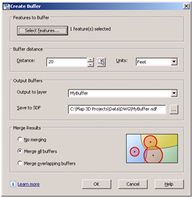
Ribbons, menus, tool bars, dialog boxes and palettes are easy to use and intuitive compared to using the command-line in AutoCAD Map 3D. For example, the Create Buffer dialog box (refer to my other buffer related posts), allows you to choose the features to be buffered, indicate the buffer distance, and specify other buffer creation options – and all with just a point-and-click of the mouse and minimal input from the keyboard.

Such methods are fine in an interactive mode when we need to manually create buffers. However, if you are writing macros to help automate the process, you need a command-line alternative that avoids launching a dialog box. To do this for our Create Buffer example, simply precede the command name, MAPFDOBUFFERCREATE, with a hyphen when you enter the command on the command-line. Here’s how to create a 20ft buffer via the command-line:
  1. At the command line enter –MAPFDOBUFFERCREATE (note the minus sign) and press Enter. The following prompt appears:
    Buffer create options [Input/Distance/Merging/Output/Go]:

  2. Enter ‘D’ then 20 to enter the buffer distance.
    Buffer create options [Input/Distance/Merging/Output/Go]: D
    Enter a buffer distance in Feet <>: 20

  3. Enter ‘M’ and then ‘S’ to ensure that multiple buffers are merged into a single feature.
    Merge buffers [None/Single/Overlapping]: S
    A single output buffer will be created

  4. Enter ‘I’ then select the features to be buffered.
    Buffer create options [Input/Distance/Merging/Output/Go]: I
    Select objects: 1 found
    Select objects:

  5. Enter ‘G’ to create the buffer as specified.
    Buffer create options [Input/Distance/Merging/Output/Go] : G
This technique allows you to use Create Buffer tool in macros, scripts, custom toolbars and workflows. In fact, the hyphen can be used for other selected AutoCAD Map 3D and AutoCAD dialog boxes including the ones listed below.

Layer Properties Manager
Command: -Layers
Prompt: [?/Make/Set/New/Rename/ON/OFF/Color/Ltype/LWeight/MATerial/Plot/Freeze/Thaw/LOck
/Unlock/stAte/Description/rEconcile]:


Block Definition
Command: -Block
Prompt: Enter block name or [?]:

Drawing Cleanup
Command: -MapClean
Prompt: Enter profile name to load:

Attach Object Class Definition File
Command: -AttachDef
Prompt: Enter name of object definition file:

In addition, certain system variables can also be used to affect the display of dialog boxes. For example, the EXPERT variable controls the display of warning dialog boxes. When the value of EXPERT is set to ‘0’, warnings and prompts are issued normally; when EXPERT is set to a value between ‘1’ and ‘5,’ specific warnings and prompts are suppressed.

Another useful system variable is FILEDIA. This variable controls the display of dialog boxes used with commands that read and write files. When the value of FILEDIA is set to ‘0’, command-line prompts are used to prompt for file names; when FILEDIA is set to ‘1’, dialog boxes are used.

Thursday, August 13, 2009

Learn Geospatial Analysis at AU2009

Autodesk University 2009 (AU2009) will be held December 1-3, 2009 at the Mandalay Bay Resort, Las Vegas. AU2009 is one of my favorite learning events of the year and the perfect opportunity to connect with professionals from all over the world and explore new ideas, technologies and workflows. Early registration for AU2009 commenced on August 12.

I’m thrilled to be participating at this event and happy to once again have the pleasure of facilitating a class on geospatial analysis. If you are an engineering, CAD or GIS professional; if you are an existing AutoCAD Map 3D user; or simply interested in learning how to analyze your CAD drawings and geospatial data; check out my 90-minute class entitled, “Analyze This! How to use AutoCAD Map 3D for Geospatial Analysis”. The topics that will be covered include:

  • Enhanced overlay capabilities and the new workflow framework
  • Databases, tabular joins and the expression builder
  • Thematic mapping techniques
  • Geospatial buffers and point, line and polygon topologies
  • 3D surfaces
If you have a preference for the type of analysis that you want discussed and demonstrated during this class, please register your vote in the polling question entitled, Pick your AU2009 Topic, which is located to the right of this post and/or leave a comment.

If you’re going to be attending AU2009, be sure to register for Class ID: GS314-2 and please say “Hi”. I look forward to meeting you!

Thursday, August 6, 2009

Los Angeles Water Goes Digital

My last post highlighted a series of webcasts aimed at the water and wastewater industry for improving data access, data confidence and utility. Well, on a similar topic, check out the August 2009 Issue of WaterWorld which highlights the Los Angeles Department of Water and Power's (LADWP) implementation of Autodesk’s geospatial software for its water system.

Read how
LADWP was able to use AutoCAD Map 3D and AutoCAD Raster Design to complete work faster, with fewer employees; reduce data errors; decrease time and money spent on training staff; and bring 100 years of detailed paper maps into a massive digital data system.

"We accept and deliver municipal data in its native ESRI format with no need for conversion. Previously, data conversion often resulted in errors or lost information. The new technology eliminated that risk.”

Kien Hoang, Manager, LADWP’s Water GIS group

Wednesday, August 5, 2009

How to Keep both Water and Data Flowing with AutoCAD Map 3D

My colleagues Peter Southwood, Neal Niemiec and I recently had the pleasure of participating in a series of webcasts, hosted by DLT Solutions, Inc., on the topic of using AutoCAD Map 3D to improve data access, data confidence and utility of water and wastewater data. Descriptions and links to the archived webcasts appear below.

Analyzing your Water/Wastewater Data with AutoCAD Map 3D
Presenter: Michael Schlosser, Autodesk
AutoCAD Map 3D is a leading engineering platform for creating and managing your water/wastewater design information. However, AutoCAD Map 3D also has powerful querying and analysis capabilities that help you to examine your water/wastewater networks in new and useful ways. This presentation shows how queries, thematic mapping, buffers, and overlay analysis can be used to better leverage your water/wastewater data.
Recorded on July 29, 2009
Length: 50 min
Link to Webcast:
http://www.dlt.com/Analyze-Water-Archive

Improving Data Confidence with AutoCAD Map 3D for Water/Wastewater
Presenter: Neal Niemiec, Autodesk
Managing water and wastewater systems within budget and to agreed upon service levels requires reliable information about the network throughout the infrastructure lifecycle. However, this requirement is threatened by a lack of data standards which can negatively impact budgets, operations, and maintenance activities. AutoCAD Map 3D improves data confidence with industry specific attribute fields, symbology and classification templates. This presentation focuses on the water/wastewater utility toolkits for creating and maintaining data according to specified standards.
Recorded on July 14, 2009
Length: 41 min
Link to webcast:
www.dlt.com/autodesk/DataConfidence-Archive

Improving Access to your Water/Wastewater Data with AutoCAD Map 3D
Presenter: Peter Southwood, Autodesk
Access to current and accurate data about your water/wastewater network is crucial for sound decision making. AutoCAD Map 3D aggregates critical CAD, GIS and utility data for field, management and regulatory purposes. This presentation focus on how to improve data access and addresses connecting to data using Feature Data Objects (FDO), attaching to DWG files, importing/exporting foreign CAD/GIS data sources and creating PDF/DWF files.
Recorded on June 22, 2009
Length: 58 min
Link to webcast:
www.dlt.com/Improve-Access-Archive

Sunday, August 2, 2009

How to use Negative Distances in your Geospatial Buffer Analysis

Geospatial buffer analysis involves generating a polygon at a specified distance from a proposed feature to determine proximity. For example, a 100m buffer around a point feature creates a circle with a 100m radius. Similarly, a 50m buffer around a polygon feature creates a larger polygon – a polygon that encompasses the source feature.

However, did you know that you can also use a negative distance to create a buffer? That’s right! When you use a negative distance, such as -25m, to buffer a polygon feature, the result is a smaller polygon – a polygon that is inside the source feature.

Consider the following example where the objective is to determine the area of shoreline habitat available for a certain species of wildlife. The species in question has been observed not to forage beyond 100m from shore and includes a riparian buffer of 25m as part of its habitat. To compute the total area of habitat available to this species requires the creation of two buffers and a polygon overlay operation. The first buffer (ie BufferOutside25) is created at a distance of +25m and represents the riparian buffer. The second buffer (ie BufferInside100) is created at a distance of -100m and represents the forage extent. A polygon overlay analysis of type subtract is then used to determine the zone of available habitat where:

HabitatZone = BufferOutside25 – BufferInside100

The total area of habitat available is equal to the area of the zone of available habitat (ie HabitatZone).

Check out the video to see the process in action with AutoCAD Map 3D.

Monday, July 20, 2009

Engineering GIS in LEED for Neighborhood Development

Leadership in Energy and Environmental Design (LEED) is a certification program that encourages the adoption of sustainable design, construction and operation practices as applied to buildings and communities. Think of LEED as a way of promoting a green approach to community development.

From a civil engineering perspective, LEED for Neighborhood Development (
LEED ND) is an opportunity to bring together engineering design and GIS analysis methods in order to meet a set of documented requirements for achieving LEED certification. For example, the Smart Location and Linkage category encourages brownfield developments to reduce urban sprawl. Maximum credit can be attained if the project is located in a previously developed infill site that is also in a high-density area. In this case, high-density is a function of the number of street intersections within a half-mile of the project boundary.

To determine how well a project complies with these criteria, we can apply an
Engineering GIS approach that leverages both CAD and GIS data. First, rather than using an import/export method to bring together the required data, FDO data providers are used to connect the GIS-based parcel and street centerline data to the CAD-based site design. Next, a geospatial buffer is created at a distance of a half-mile from the site boundary. The buffer is used to determine proximity and involves generating a polygon at a specified distance from the proposed site boundary. Finally, in this simplified example, a geographic query is used to determine the number of intersections within the buffer and this number is compared to the LEED criteria.

Some of the benefits of this approach include the following:

  • Data conversion and data redundancy can be avoided as a result of using FDO data providers to connect to the data directly rather than relying on an import/export process.

  • Efficiency is improved as a result of applying an approach that embraces CAD tools for site design and geospatial tools for analysis all in one software platform.

  • Better designs are possible because more design alternatives can be evaluated against LEED criteria.
Check out the video to see the process in action using AutoCAD Map 3D.


Friday, July 10, 2009

Cowboys, Barbeque and Geospatial Analysis

Yee Haw! It’s Stampede Week in Calgary, Alberta and what better way to celebrate than to combine Stampede attire (ie cowboy hat, jeans, big belt buckle and boots) with a seminar on Geospatial Analysis. Well, it seemed like a crazy idea; however, the folks at Autodraft, Inc have a great sense of fun. So, when I was given the opportunity to talk about my favorite topic of Engineering GIS and CAD/GIS integration, I jumped at the chance.

In spite of the Stampede traffic, the rain and the tornado watches, folks came out in droves to learn how to analyze their CAD drawings and geospatial data using the powerful geospatial analysis tools found in Engineering GIS. With the help of my pardner "Cowboy Bob", we delivered a seminar entitled "Geospatial Analysis for the Egnineering and CAD Professional". We used AutoCAD Map 3D, AutoCAD Raster Design and Autodesk Topobase to demonstrate numerous geospatial techniques including…

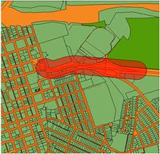
Sample Buffer Analysis performed with AutoCAD Map 3D
  • Queries and how to use them to get more information from CAD drawings and GIS data sources
  • Drawing cleanup tools and why they are necessary to ensure the accuracy and correctness of CAD and GIS data
  • Topology, it’s importance for CAD and GIS users alike and how to create topologically correct features
  • Spatial analysis such as network traces and their use with CAD and GIS data
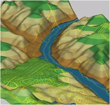
  • Polygon overlay and its power to reveal new patterns in CAD and GIS dataSample 3D Surface Analysis performed with AutoCAD Map 3D
  • Buffer analysis and why it’s sometime the best way to determine spatial proximity
  • 3D surfaces and how to analyze them for height, slope and aspect
  • Raster to vector conversion and how to combine scanned CAD drawings, maps and aerial imagery with vector-based CAD and GIS data
  • And more…
After the presentation, we all moseyed on down to the Autodraft corral for a great Stampede barbeque, refreshments and conversation.

A fun and informative Yee Haw time was had by all!


Friday, June 26, 2009

New Online Resource: GIS Skills for Engineers

Over the last several months, I have had the pleasure of facilitating a number of seminars in Canada and the United States aimed at demonstrating the six crucial GIS skills needed by Engineering and CAD professionals. I have blogged about this seminar series in the past. This time I want to call your attention to a great resource entitled GIS Skills for Engineers that is now available via the web. This resource is part of Autodesk's help documentation for AutoCAD Map 3D and highlights a number of important GIS skills including:

Data Preparation
Data Conversion
Data Access
Data Editing
Data Management
Styling and Theming Features
Analysis
Sharing Data with Others
Map Layout and Cartography
Printing, Plotting, and Publishing

The best part of GIS Skills for Engineers is the accompanying animations which demonstrate the skills in action. For example, if you wanted to know how to perform a polygon overlay analysis to determine which parcels in a city fall within zones classified as “Retail”, check out this animation.

Monday, April 6, 2009

Free Engineering GIS Software for Unemployed

Autodesk, Inc recently announced a new program called the Autodesk Assistance Program. According to Steve Blum, Senior Vice President America's Sales for Autodesk, the program is designed to help the unemployed advance their career during this challenging job market.

Among other things, the program offers:

  • Free software
  • Free online training
One of the software packages offered by Autodesk through this program is AutoCAD Civil 3D.

Recall that in some of my previous
posts, I discussed the need for Engineering GIS. Well, built on top of AutoCAD Map 3D and AutoCAD, AutoCAD Civil 3D is a true engineering GIS platform and complies with all five Engineering GIS requirements, namely:
  • Data throughout the lifecycle
  • Native data access
  • Engineering design tools
  • Geospatial tools
  • Accurate renderings
If you are currently unemployed and interested in investing some of your time to retain existing skills or get the new Engineering GIS skills you need, check out the details of this program here or be sure to tell a friend in need.